Contact
igus® Ltd.
| Option: 1 rail, 1 carriage | ||
|---|---|---|
| sy + sz | < | 2 Lx - Y0 |
| ay + az | < | 2 Lx - Y0 |
| sy | < | 5 Zm |
| sz | < | 5 Zm |
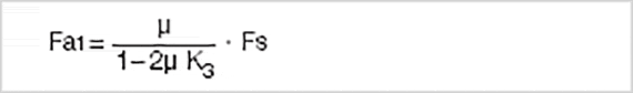
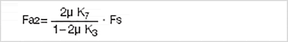
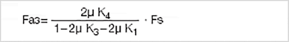


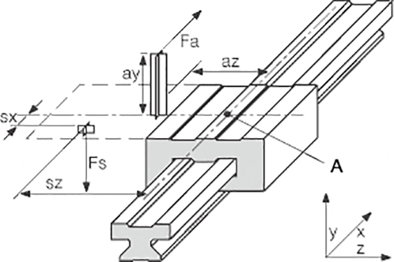
| Fa: | Driving power | [N] |
| Fs: | Mass force | [N] |
| Fy, Fz: | Bearing load in y- or z-direction | [N] |
| sx, sy, sz: | Clearance of the mass force in x-, y- or z-direction | [mm] |
| ay, az: | Clearance of the driving power in y- or z-direction | [mm] |
| wx: | Clearance of the carriage on a rail | [mm] |
| LX: | Constant based on the installation size | [mm] |
| Zm: | Constant based on the installation size | [mm] |
| Y0: | Constant based on the installation size | [mm] |
| b: | Clearance of the guide rails | [mm] |
| µ: | Coefficient of friction, µ = 0 in static loads, µ = 0.2 in dynamic loads | |
| ZW: | Number of carriages per rail |
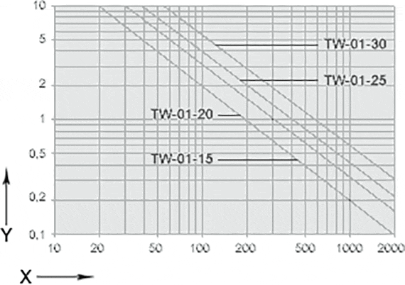
| Order no. | LX | ZM | Y0 |
|---|---|---|---|
| [mm] | [mm] | [mm] | |
| TW-01-15 | 29 | 16 | 11,5 |
| TW-01-20 | 35 | 23 | 15,0 |
| TW-01-25 | 41 | 25 | 19,0 |
| TW-01-30 | 49 | 29 | 21,5 |
| 1 rail, 1 carriages | |
|---|---|
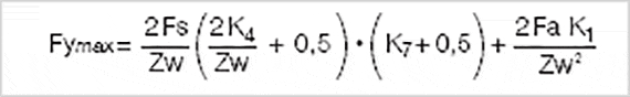
| K1 | |(ay+Y0)/Lx| |
| K2 | (sy+Y0)/Lx |
| K3 | |az/Lx| |
| K4 | |sx/Lx| |
| K5 | sz/Lx |
| K6 | |(sy+Y0)/Zm| |
| K7 | |sz/Zm| |
| Order no. | Fymax, Fzmax [N] |
|---|---|
| TW-01-15 | 2000 |
| TW-01-20 | 3700 |
| TW-01-25 | 5000 |
| TW-01-30 | 7000 |