Change Language :
twisterchain® - circular and spiral movements, can be opened on both sides
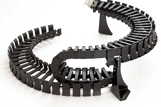
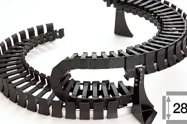
The twisterchain® product line offers a wide selection for circular movements and is available in four sizes. Modular in width and radius, therefore flexible in applications where rotary and spiral movements up to 360° and more with high loads and high running smoothness are required. twisterchain® applications are available with guide trough, which has the following advantages: guidance of the energy chain, reduced abrasion of the energy chain, optimum running smoothness, rotation angle up to 360° from stock.
- Stable, high additional loads possible, smooth running, weight-optimised
- Rotational speeds up to 1m/s and more
- Circular/spiral movements up to 360° from stock (up to 400° upon request)
- Cable-friendly, smooth interior can be opened crossbar in inner and outer radius
- Successfully tested over 1 million cycles in the igus® laboratory
Delivery programmes
crossbar removable in inner and outer radius
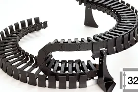
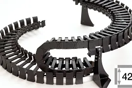
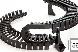
twisterchain® generally valid
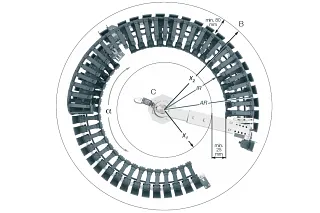
For machine elements that move in a circle both to the left and to the right, the rotation angle is calculated by adding the two angles.


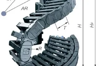
AR = outer radius energy chain
X1 = Inner mechanical engineering
HF = e-chain® Height incl. 50mm free space
hi = inner height energy chain
IR = inner radius energy chain
X2 = Outer mechanical engineering
HH = e-chain® height
ha = outer height energy chain
R = bend radius energy chain
T = pitch
K = Surcharge for bend radius
α = rotation angle
twisterchain general information
For machine elements that move in a circle both to the left and to the right, the rotation angle is calculated by adding the two angles.
Legend
B = Outer limit
C = Machine
D = fixed end
E = Upper limit
AR = outer radius chain
IR = inner radius chain
R = bend radius chain
X1 = Inner engineering space
X2 = AR chain incl. clearance
T = pitch
HF = Chain height incl. 50 mm clearance
H = chain height
K = Surcharge for bend radius
hi = inner height of the chain
ha = outer height of the chain
α = rotation angle


Recommendations for designing the twisterchain new without additional components
| Series | AR [mm] | FZmax. [kg/m] α0°- 180° | FZmax. [kg/m] α180°- 360° | v at AR permissible [m/s] | a at AR max. [m/s2] |
|---|---|---|---|---|---|
| TC32 | 400 | 4 | 2 | 1 | 2 |
| 500 | 4 | 2 | 1 | 2 | |
| 600 | 4 | 2 | 1 | 2 | |
| TC42 | 400 | 6 | 3.6 | 1 | 2 |
| 500 | 6 | 3.6 | 1 | 2 | |
| 600 | 6 | 3.6 | 1 | 2 | |
| 650 | 5 | 2.7 | 1 | 1.5 | |
| 750 | 4 | 1.8 | 1 | 1 | |
| 850 | 4 | 1.8 | 1 | 1 | |
| TC56 | 650 | 8 | 5 | 1 | 2 |
| 750 | 8 | 5 | 1 | 2 | |
| 850 | 8 | 5 | 1 | 2 |
Selecting the right twisterchain®

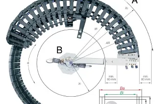
Legend
A = Outer limit
B = Machine
C = Upper limit
a = Acceleration
α = rotation angle
AR = outer radius e-chain®
Ba = e-chain®® -outer width
Bi = e-chain®® -inner width
FZmax = max. additional load
H = Nominal clearance height
ha = e-chain®® -outside height
hi = e-chain®® -inner height
HF = Required clearance height incl. 50 mm free space
IR = Inner radius e-chain®
K = Surcharge for bend radius
for length calculation n = Number of chain links
R = bend radius
T = pitch
v = Travelling speed
X1 = Inner machine installation space
X2 = outer radius incl. clearance
RLK = Distance pivot point/fixing holes outside
twisterchain® is generally valid:
For machine elements that move in a circle both to the left and to the right, the rotation angle is calculated by adding the two angles.
The following clearances are essential for the chain to function correctly:
**IRmin. = X1 + 80 mm
X2 min. = AR + 80 mm
HF = H + 50 mm**
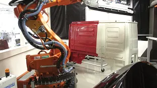
Realised in practice: twisterchain in multiple robots
A twisterchain® proves its worth in the circular movement of the rotary axis of a multiple robot. Here it is used for a rotary movement of 180°. hose and cable are guided securely, abrasion is significantly reduced and running smoothness is increased.
Contact us
Contact details

Justin Leonard01604 677240Contact us
Opening hours
Office hours
Monday to Friday from 8 am - 8 pm.
Live chat:
24h